
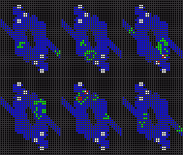
For a while now I have a simple idea of designing adjustable universal speed ship, based on a circuit.
The idea is illustrated below: we use a circuit to decode operations, and slow down the tape to a speed we like. Then we code the whole construction of this circuit into salvo that moves with c/4 which is constructed in the front of the ship. This salvo has the whole circuit built in it using gliders, i.e. it's like dried salvo but instead SLs it uses gliders to commit operations (just like Caterpillar codes the first lanes, this design codes the whole circuit).
This idea can work for diagonal as well as for orthogonal ships. But for orthogonal, we will need to slow salvo construct the universal helix, for diagonal we don't need anything complex, just the usual slow salvo. For the helix we can just using gliders, convert SL ->horizontal *WSS -> vertical *WSS -> SL, so this SL can move at any speed close to c/4.
Circuit based ship working notes
Circuit based ship working notes
- Attachments
-
- Universal Ship.png (18.07 KiB) Viewed 4416 times

Re: Circuit based ship working notes
A few quick questions:simsim314 wrote:For a while now I have a simple idea of designing adjustable universal speed ship, based on a circuit.
1) As the diagram stands, it seems like this will be an adjustable-speed replicator, or rather a linear propagator. Would you add some shutdown and self-destruct capability for the old circuit loops?
2) Could an orthogonal design just use *WSSes in place of gliders, maybe for about the same cost these days as slow-salvo constructing the universal helix? Or is this just intended to be a diagonal-or-orthogonal design?simsim314 wrote:This idea can work for diagonal as well as for orthogonal ships. But for orthogonal, we will need to slow salvo construct the universal helix, for diagonal we don't need anything complex, just the usual slow salvo. For the helix we can just using gliders, convert SL ->horizontal *WSS -> vertical *WSS -> SL, so this SL can move at any speed close to c/4.
3) Can you be more specific about the universal helix? What exactly would a near-c/4 circuit do to push its next target out to (2n,n), for example?
Re: Circuit based ship working notes
First of all I was thinking about single lane design, using simeks recipes. Obviously the self destruct would be triggered by the last glider that will remove the construction target and shoot a glider back to trigger the self destruct. There is also an option to push the target far forward and shoot the circuit down using gliders that return from the target. A combination of the two could also be a possibility - i.e. triggering minimal self destruct circuit with several gliders.dvgrn wrote:Would you add some shutdown and self-destruct capability for the old circuit loops?
I really didn't understand the question. I meant to use *WSSes as a tape, that construct a dried universal helix, and then add extra *WSSes to construct the circuit, after universal helix shoots a glider. Just rotate the scheme by 45 degrees, and replace gliders by *WSS, and obviously add universal helix just in order to provide an option to move with any desirable speed "in front" of the ship.dvgrn wrote:Could an orthogonal design just use *WSSes in place of gliders, maybe for about the same cost these days as slow-salvo constructing the universal helix?
This is basically the same design as caterpillar, just extra *WSS will construct the whole circuit instead of a single blinker.
There also can be an option to use construction from two directions with quite low cost - just add an extra output and a trigger that can enable one side and disable the other.
This design works only for strictly diagonal or orthogonal ships. So the next target should be at (n, n), this is done in 3 steps:dvgrn wrote:3) Can you be more specific about the universal helix? What exactly would a near-c/4 circuit do to push its next target out to (2n,n), for example?
1. SL + salvo -> horizontal *WSS
2. horizontal *WSS + salvo -> vertical *WSS
3. vertical *WSS + salvo -> SL + glider (helix trigger)
To adjust timing, step 2 could be done in 2 substeps:
2.1 horizontal *WSS + salvo -> SL
2.2 SL + salvo -> vertical *WSS
- Attachments
-
- Diagonal Universal Helix.png (7.16 KiB) Viewed 4370 times
Re: Circuit based ship working notes
I think the picture is getting clearer now, but I'm probably still confused. How much circuitry will have to be in each of the circuits that you have marked with pentagons, and how many of of those circuits would there be in the (orthogonal or diagonal) row?
(I got a momentary picture of a very long line of identical constructor circuits, each one timed to contribute one cycle of a universal helix, to improve the period of the whole pattern -- but I think that's a whole different idea, and maybe a silly one.)
Maybe this will help me: please could you add a few more directional arrows to your original diagram? It seems like you're having the "glider tape" move northeast, and the salvos activating your universal helix would also move northeast...? But then I'm having trouble seeing how the construction would get completed on the newest, northeast-most circuit, in time to catch the first gliders on the "glider tape".
So I must just not be understanding the idea yet, or else there's more built-in logic required in the circuits than I'm thinking. The output of pre-constructed freeze-dried slow salvos is hard for me to think about; it might help if I could see where they're being constructed, where they're being triggered from, and where the output goes.
------------------------------
Seems like this is going to end up a fairly ambitious size, for a first spaceship pattern that uses freeze-dried slow salvos. I'd like to try a first project that's as small as possible, something that Golly can handle fairly easily (and hopefully run away with). Two ideas have been competing for space in my head this week:
1) an adjustable-period oscillator with 100% volatility (easy, but kind of silly);
2) a true [but very slow] (2,1)c/N knightship -- I might actually start a thread on that one.
I should probably just go back and start work on the quadratic replicator project again, though -- or at least the square Orthogonoid. Either of those can make really good use of 90-tick single-channel construction, but I don't think they will really need much in the way of freeze-dried slow salvos.
(I got a momentary picture of a very long line of identical constructor circuits, each one timed to contribute one cycle of a universal helix, to improve the period of the whole pattern -- but I think that's a whole different idea, and maybe a silly one.)
Maybe this will help me: please could you add a few more directional arrows to your original diagram? It seems like you're having the "glider tape" move northeast, and the salvos activating your universal helix would also move northeast...? But then I'm having trouble seeing how the construction would get completed on the newest, northeast-most circuit, in time to catch the first gliders on the "glider tape".
So I must just not be understanding the idea yet, or else there's more built-in logic required in the circuits than I'm thinking. The output of pre-constructed freeze-dried slow salvos is hard for me to think about; it might help if I could see where they're being constructed, where they're being triggered from, and where the output goes.
------------------------------
Seems like this is going to end up a fairly ambitious size, for a first spaceship pattern that uses freeze-dried slow salvos. I'd like to try a first project that's as small as possible, something that Golly can handle fairly easily (and hopefully run away with). Two ideas have been competing for space in my head this week:
1) an adjustable-period oscillator with 100% volatility (easy, but kind of silly);
2) a true [but very slow] (2,1)c/N knightship -- I might actually start a thread on that one.
I should probably just go back and start work on the quadratic replicator project again, though -- or at least the square Orthogonoid. Either of those can make really good use of 90-tick single-channel construction, but I don't think they will really need much in the way of freeze-dried slow salvos.
Re: Circuit based ship working notes
It's not such a bad idea. We can have two components:dvgrn wrote:I got a momentary picture of a very long line of identical constructor circuits, each one timed to contribute one cycle of a universal helix, to improve the period of the whole pattern -- but I think that's a whole different idea, and maybe a silly one.
1. A tape that moves a target diagonally.
2. Universal helix gun, that has a sequence that shoots at the target and generates universal helix, every N generations.
This will allow to code "anything" quite easily. But I think this idea will cost too much.
You understand everything correctly. Each circuit can "hold back" a glider for any time it needs. Think of the pentagon as a regular duplicator, combined with few snarks that hold the glider back for any number of ticks we need. On the other hand we can space the circuits at any distance we like. Those two timing mechanism can allow a great deal of control over the speed of the ship.dvgrn wrote:I'm having trouble seeing how the construction would get completed on the newest, northeast-most circuit, in time to catch the first gliders on the "glider tape".
Attached.dvgrn wrote:please could you add a few more directional arrows to your original diagram?
------------
As for other projects - I would suggest to start from scripts that combine all our knowledge, firstly in the simplest way possible. With good enough toolset of scripts, quadratic replicator wouldn't be such a big of a deal, and the orthogonoid would be completed already and only in need of optimization.
The scripts are as follows:
1. Given a pattern with SLs, make slow salvo construction recipe out of it. Just some recipe.
2. Given a slow salvo - create the glider stream that codes the operations of a single lane.
This will allow us to separate forces:
1. One important task would be to optimize the two scripts as much as possible.
2. Using the best existing scripts, thinking of the best design i.e. the fine tuning part, fitting it all together.
I think script #1 shouldn't be too hard of a problem. As for construction order of the script, I would suggest to start with greedy algorithm which is less than ~50% away from the optimal (next construct the closest valid SL).
For starters this script can also fail from time to time, it should work in 95% of the cases, while people could work on the rest 5% after the script is working most of the time. Obviously some special cases should be introduced like eater2 with eater1 in close proximity etc.
Another less crucial scripts might be:
3. Drying out any synthesis.
4. Multi glider self destruct.
5. Two directions synchronized gliders synthesis from SL list.
- Attachments
-
- Universal Ship.png (19.32 KiB) Viewed 4348 times